HVAC & R Techniques
Heating, Ventilation, Air Conditioning, and Refrigeration (HVAC & R) systems rely on fundamental thermodynamic processes that modify air temperature, moisture content, and enthalpy to create comfortable and efficient indoor environments.
To visualize and understand these processes, the psychrometric chart is one of the most powerful tools in the HVAC industry. Each technique corresponds to a specific path or transformation on the chart.
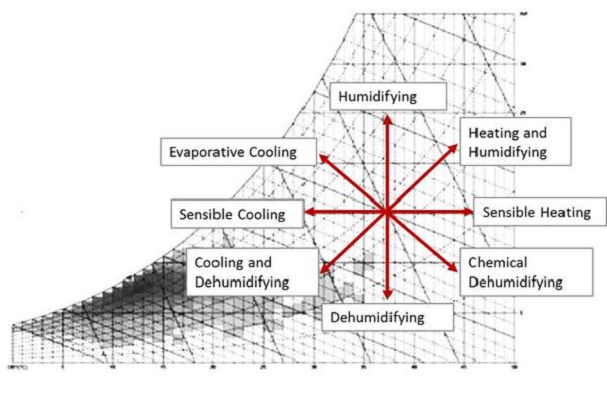
Below are the essential HVAC & R heating and cooling techniques, explained using their psychrometric representations.
1. Sensible Heating →
Sensible heating increases the dry-bulb temperature of air without changing its moisture content.
On the psychrometric chart, this process is represented by a horizontal line moving to the right.
Applications:
- Electric heaters
- Hot water coils
- Steam coils
- Heating elements in AHUs and FCUs
2. Sensible Cooling ←
Sensible cooling decreases the dry-bulb temperature with no change in humidity ratio.
On the psychrometric chart, it appears as a horizontal line moving to the left.
Applications:
- Chilled water coils
- DX cooling coils operating above dew-point
- Air-side economizers
3. Heating and Humidification ➚
Used primarily in cold climates, this process increases both temperature and humidity.
On the chart, it moves upward and to the right.
Applications:
- Steam humidifiers
- Atomizing humidifiers
- Electric humidification + heating coils
4. a. Cooling and Dehumidification ⬋
When the cooling coil surface temperature is below the dew-point, moisture condenses out of the air.
The process moves downward and to the left on the psychrometric chart.
Applications:
- DX cooling coils
- Chilled-water cooling coils
- Refrigeration-based dehumidification
4. b. Indirect Evaporative Cooling ⬋
Heat is removed through a secondary air stream without adding moisture to the conditioned air.
On the chart, the process moves downward-left with a decrease in humidity ratio.
Applications:
- Heat recovery ventilators
- Evaporative-assisted cooling systems
5. Evaporative Cooling ⬉
Evaporative cooling reduces air temperature while increasing humidity, with the total enthalpy remaining nearly constant.
On the chart, this follows a constant wet-bulb (or constant enthalpy) line.
Applications:
- Direct evaporative coolers
- Cooling towers (air side)
- Pad-and-fan systems
6. Chemical Dehumidifying (Desiccant Dehumidification) ⬊
Desiccants remove moisture by chemical adsorption, causing a slight temperature increase.
On the chart: moves down (less moisture) and slightly right (increased temperature).
Applications:
- Industrial drying
- Cleanrooms
- Low-humidity or high-temperature processes
7. Air Mixing
Mixing two air streams results in a final state point located on the straight line connecting the two conditions, based on mass-weighted averaging.
Applications:
- Outdoor air + return air mixing in AHUs
- Energy recovery mixing strategies
8. Reheating
After dehumidification, air is sometimes too cold. Reheating raises its temperature while humidity remains unchanged.
Psychrometric path: horizontal line to the right after a cooling–dehumidification process.
Applications:
- Reheat coils in VAV systems
- Heat recovery reheating
- Hot-gas reheat in DX systems
9. Compression Refrigeration
Evaporators cool and dehumidify air, following a combined sensible + latent cooling path.
Condensers reject heat to the outdoor environment in refrigeration cycles.
Applications:
- Split AC units
- VRF/VRV systems
- Commercial refrigeration systems
10. Absorption Refrigeration (NH₃–H₂O and H₂O–LiBr)
Absorption refrigeration systems provide cooling by using heat energy instead of mechanical work. Unlike vapor-compression systems—where a compressor drives the cycle—absorption systems use a thermal generator, a solution pump, and an absorber to circulate refrigerant.
They are ideal in buildings where waste heat, solar heat, or industrial thermal energy is available.
Absorption systems operate based on two well-known working pairs:
A. Ammonia–Water (NH₃–H₂O) Absorption Refrigeration
Working Pair:
- Refrigerant: Ammonia (NH₃)
- Absorbent: Water (H₂O)
Process Summary:
- Generator (Heat Source): Heat separates ammonia vapor from the strong ammonia–water solution.
- Condenser: Ammonia vapor releases heat and condenses to a high-pressure liquid.
- Evaporator: Liquid ammonia evaporates, absorbing heat and creating the cooling effect.
- Absorber: Low-pressure ammonia vapor is absorbed back into water.
- Pump: The strong solution returns to the generator.
Applications:
- Industrial refrigeration
- Low-temperature cooling (below 0°C)
- Cold storage / food processing facilities
- Off-grid or waste-heat-powered cooling
Advantages:
- Can operate at very low temperatures
- Uses heat instead of electricity
- Effective for industrial facilities
B. Water–Lithium Bromide (H₂O–LiBr) Absorption Chillers
Working Pair:
- Refrigerant: Water (H₂O)
- Absorbent: Lithium Bromide (LiBr)
Important:
Because water is the refrigerant, the system operates at deep vacuum to allow water to evaporate at low temperatures (≈ 6–7°C).
Process Summary:
- Generator (Heat Input): Heat drives water vapor out of the LiBr solution.
- Condenser: The water vapor condenses and rejects heat.
- Evaporator: Water evaporates under vacuum, producing chilled water.
- Absorber: LiBr solution absorbs water vapor, releasing heat that must be removed.
- Pump: Concentrated solution returns to the generator.
Applications:
- Hospitals
- District cooling plants
- University campuses
- Data centers
- Facilities with steam, hot water, or solar thermal systems
Advantages:
- Extremely quiet (no compressor)
- High reliability
- Very low electrical demand
- Ideal for large chilled-water systems
NH₃–H₂O vs. H₂O–LiBr Absorption Systems (Quick Comparison)
| Feature | NH₃–H₂O | H₂O–LiBr |
|---|---|---|
| Refrigerant | Ammonia | Water |
| Absorbent | Water | Lithium Bromide |
| Cooling Range | Below 0°C | 6–13°C (chilled water) |
| Safety | Ammonia is toxic | LiBr non-toxic but crystallizes |
| Heat Source | High temperature | Low–medium temperature |
| Typical Use | Industrial freezing | Building HVAC chillers |
11. Horse Shoe (Bypass + Reheat Control Method)
The Horse Shoe Technique is an HVAC air-conditioning control method that manages temperature and humidity by combining a cooling coil, air bypass, and reheat in a configuration shaped like a horseshoe.
This technique is used when precise humidity control is required, especially in spaces where both comfort and moisture reduction are essential.
How the Horse Shoe Technique Works
- Cooling Coil (Primary Path)
- A portion of return air passes through the cooling coil.
- Moisture is removed as the air is cooled below its dew point.
- This provides latent cooling (dehumidification) plus some sensible cooling.
- Bypass Air Path
- Another portion of the return air bypasses the cooling coil entirely.
- This bypassed air retains higher temperature and moisture ratio.
- Mixing Section (Horse Shoe Loop)
- The cold/dehumidified air from the coil mixes with the warm bypass air.
- This “horseshoe” flow path allows precise control of supply air temperature while still achieving humidity reduction.
- Optional Reheat
- When very low humidity levels are required, the mixed air may be reheated to avoid overcooling the space.
- Reheat can be electric, hot water, or waste heat from condensers.
When the Horse Shoe Technique Is Used
- Spaces that require humidity control without excessive cooling, such as:
- Hospitals and clinics
- Laboratories
- Museums and archives
- High-occupancy zones
- Buildings with variable ventilation requirements
- Situations where air must remain above a minimum temperature while still removing moisture.
Advantages
- Provides stable humidity control even under varying load conditions.
- Reduces overcooling by blending bypass air with coil air.
- Flexibility to add reheat only when required.
- Improves comfort by balancing latent and sensible loads.
Considerations
- Bypass ratios and mixing must be carefully designed for the desired supply air state.
- Reheat increases energy use if not controlled properly.
- Requires proper duct layout to form the horseshoe-shaped bypass and return loop.
Psychrometric Interpretation
On the psychrometric chart:
- The portion of air passing through the cooling coil follows a cooling + dehumidification path (downward-left).
- Bypass air remains near its original condition.
- The mixed air state point falls between the two paths, resulting in a controlled supply air temperature with reduced humidity.
- If reheat is used, the final condition moves horizontally to the right (sensible heating).
12. Run-Around Coil System (Run-Around Loop)
The Run-Around Coil System is an energy-recovery technique used in buildings where the exhaust air and outdoor (fresh) air streams are physically separated and cannot be connected through a typical heat recovery unit. In this method, two coils—one placed in the exhaust air path and the other in the outdoor air path—are connected by a closed loop of circulating fluid (usually water or a water-glycol mixture).
The fluid absorbs heat from the warm air stream and transfers it to the cooler air stream, improving overall system efficiency without mixing the two airstreams. This allows heat recovery across large distances or between separate mechanical rooms.
Applications
- Buildings with strict air-quality requirements (hospitals, laboratories, cleanrooms)
- Spaces where air streams cannot be mixed
- Facilities with separated air-handling units (AHUs)
- Retrofits where installing a typical heat-recovery ventilator is not possible
Advantages
- No cross-contamination between supply and exhaust air
- Flexible installation even across long distances
- Reduces heating or cooling loads on AHUs
- Simple, durable, and low-maintenance technology
Limitations
- Lower effectiveness compared to enthalpy wheels or plate heat exchangers
- Requires pump power for fluid circulation
- Additional piping installation is needed
Overall Benefit
The Run-Around Coil System enhances building energy performance by transferring sensible heat between remote air streams, making it an effective solution for energy recovery where conventional heat-recovery devices cannot be used.
13. Optimal Insulation Diameter / Critical Insulation Radius
When insulating cylindrical components (pipes, ductwork, channels), the effect of insulation on heat transfer is not always “more insulation = less heat loss.” In certain conditions, adding a small layer of insulation may — paradoxically — increase heat loss. This is due to a phenomenon known as the “critical radius of insulation.”
What is the Critical Insulation Radius?
For cylindrical pipes (or ducts), heat loss to the ambient from the outer surface depends on:
- conduction resistance through the insulation → which increases with insulation thickness
- convection resistance at the outer surface → which decreases when the outer surface radius increases (because surface area increases)
Due to this trade-off, there is a radius (outer radius of insulation) at which the total resistance is minimal — that is, the rate of heat transfer is maximal. This radius is called the critical radius (r₍c₎).
For a cylindrical pipe, the critical radius can be approximated as:
r_c = k / h
where:
- k = thermal conductivity of insulation material (W/m·K)
- h = convective heat transfer coefficient of the surrounding medium (W/m²·K)
If the outer radius (pipe + insulation) is less than r₍c₎, adding insulation can increase heat loss. Only when the outer radius exceeds r₍c₎ does insulation begin to reduce heat loss.
What this means in practice
- For small-diameter pipes or very poor insulation materials (high k), the “critical radius” may be larger than the current pipe + insulation radius; in such cases a thin insulation layer can actually worsen heat loss.
- For larger-diameter pipes (or ducts) and typical insulation materials (low k), insulation is effective, but there is still an “optimum” thickness beyond which additional insulation yields diminishing returns in energy savings.
- For optimal design (cost vs savings), one should evaluate where the insulation radius lies relative to the critical radius — especially when insulating small-diameter pipes or ducts.
Illustrative Plot: Heat Loss vs Insulation Radius
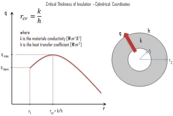
In the plot above:
- The horizontal axis (r) represents the outer radius of the pipe including insulation.
- The vertical axis (Q) represents the heat loss per unit length (or heat transfer rate).
- When r < r₍c₎, the curve rises — meaning adding insulation increases heat loss.
- At r = r₍c₎, heat loss reaches a maximum.
- For r > r₍c₎, adding insulation reduces heat loss; the larger the insulation (up to practical limits), the lower Q — but with diminishing returns.
This illustrates that there is an optimum insulation thickness/radius beyond which extra insulation brings little benefit, and below which insulation may be counterproductive.
How to Use this Concept in HVAC Design
- Calculate the critical radius (r₍c₎) for each pipe or duct: you need the insulation material’s k and the expected convective coefficient h (which depends on air flow, orientation, etc.).
- Ensure that your insulation design produces an outer radius greater than r₍c₎. If not — either increase insulation thickness or reconsider insulation approach.
- For large ducts or widely exposed pipes, consider the economic optimum insulation thickness: balance material/installation cost vs energy savings over the system lifetime.
- Always account for condensation risk, vapor barrier, fire code, maintenance and access for inspection — especially when insulation is thick.
Why This Matters for BuildingEnergyLab Readers
In many HVAC & R systems, designers and operators focus on “insulate everything thickly.” However:
- For small-diameter pipes or ducts, uncritical insulation may degrade performance.
- For large distribution networks, excessive insulation increases cost and may not yield significant additional savings.
- Understanding the critical radius / optimum insulation point helps making smart, efficient, cost-effective design decisions — improving both energy performance and lifecycle cost.
14. Insulation Best Practices: Surface Finish & Condensation Control
Effective insulation of pipes, ducts, and air channels is not just about thickness — the type and installation details matter hugely. In HVAC & R systems, two critical factors deserve special attention to ensure performance, durability, and safety.
I. Use of Reflective / Low-Emissivity Outer Surface
When insulating external or exposed ducts, pipes or channels, the outer face of the insulation should be shiny or reflective (e.g., foil-faced insulation). This finish reduces the absorption and emission of thermal radiation:
- A reflective outer surface absorbs less radiant heat from the surroundings (sunlight, warm walls, radiant sources).
- It also emits less thermal radiation back, reducing heat gain or loss through radiation.
- This is especially important for outdoor ducts/pipes, rooftop installations, or ducts running through unconditioned zones with large temperature differences.
Properly selected and installed reflective insulation helps maintain design temperatures, reduces thermal losses/gains, and improves overall energy efficiency.
II. Condensation Control & Moisture Protection for Cooling Systems
When insulation is used on chilled-water pipes, cold-air ducts or other cooling-related pipelines/channels, it’s vital to avoid dew-point condensation — moisture forming on the outer surface of insulation or on metal beneath.
If condensation is allowed:
- Water droplets can form on or inside the insulation material — this moisture may cause chemical reactions, corrosion, mold growth, or erosion of insulation over time.
- Insulation may degrade, lose its thermal performance, or even cause hygiene and maintenance issues.
To prevent this:
- Always provide a vapor barrier or moisture-resistant jacket on cold lines/ducts.
- Select insulation materials that are resistant to moisture, non-hygroscopic, and durable under potential condensation exposure.
- Ensure seams, joints and penetrations are properly sealed.
- Where necessary, include drainage or condensate management to remove any moisture that may accumulate.
Why These Best Practices Matter
- A shiny, reflective outer surface helps insulation work effectively — not just by conduction reduction but also by minimizing thermal radiation exchanges.
- For systems cooling air or water, condensation control is critical — neglecting it can undermine the insulation’s performance, shorten its lifespan, and introduce hygiene or corrosion risks.
- By paying attention to these details, HVAC & R installations remain energy-efficient, safe, durable, and low-maintenance.
15. Zoning & Variable Flow / Variable-Speed HVAC Systems
In zoning systems, the building is divided into separate thermal zones so heating and cooling are delivered only where needed. Variable-speed fans, pumps, and chillers adjust their output based on real-time demand instead of running at constant capacity. These strategies significantly reduce energy consumption, improve comfort control, and maintain optimal part-load performance of HVAC equipment.
16. Heat Recovery & Energy Recovery Ventilation (ERV/HRV) Systems
Heat-recovery and energy-recovery units capture thermal energy from exhaust air and transfer it to incoming fresh air. These systems reduce heating and cooling loads by pre-conditioning outdoor air using plate heat exchangers, enthalpy wheels, or heat pipes. When combined with proper ventilation design, heat-recovery systems greatly enhance overall building energy efficiency.
17. Heat Pump, Geothermal, and Renewable-Integrated HVAC Systems
Heat pump systems deliver heating and cooling more efficiently by transferring heat rather than generating it, while geothermal systems use stable ground temperatures for superior performance. Integrating renewable and low-temperature heat sources further improves system efficiency. These techniques reduce energy consumption, enable decarbonization, and provide high-performance alternatives to conventional boiler–chiller setups.
18. Smart Controls, Demand-Controlled Ventilation (DCV) & Predictive Operation
Smart HVAC controls optimize system operation using occupancy sensors, CO₂ monitoring, and real-time indoor conditions. Demand-controlled ventilation adjusts outdoor air intake according to actual occupancy, preventing unnecessary ventilation loads. Predictive and model-based control strategies (such as AI or MPC) anticipate changes in weather, occupancy, and building load to operate HVAC systems at maximum efficiency.
19. Thermal Mass Utilization, Night Cooling & Thermal Energy Storage
Thermal mass systems use building materials—such as concrete slabs or structural walls—to store heat or cool energy and release it gradually. Night cooling, phase-change materials, and chilled-water storage help shift cooling loads to off-peak hours and reduce peak electricity demand. These methods stabilize indoor temperatures and enhance the overall performance of HVAC systems.
20. Ductwork & Pipework Efficiency, Leakage Control, Maintenance & Commissioning
Improper duct or pipe insulation, air leakage, and unbalanced distribution systems cause significant thermal and energy losses. Proper sealing, insulation, airflow balancing, and pressure-drop-optimized design ensure efficient transport of conditioned air and chilled/heated water. Regular maintenance, cleaning, system tuning, and professional commissioning keep HVAC systems operating at their designed performance levels throughout their service life.
How These Techniques Support HVAC Design
Each HVAC process plotted on the psychrometric chart helps engineers:
- Estimate coil loads
- Size fans, ducts, pipes, and compressors
- Select appropriate heating/cooling systems
- Optimize indoor comfort and air quality
- Improve energy efficiency through correct process selection
- Understand air-side economizer and heat recovery potential